Facts & Features
Electrical Configuration (Basic Description)
Turbine system produces 3-phase "wild" AC via direct drive permanent magnet generators. This is rectified to DC via a proprietary rectifier/charge controller unit set for charging of 12/24/48VDC battery banks. Exact charge voltage is factory-set according to your battery specifications.
Connect your DC load(s) or DC/AC inverter to the battery bank.
Systems can be connected in hybrid with other energy sources such as solar, generator, grid, etc.
Operational Features (Charge Controller / Rectifier)
-
Automatic overcharge protection/cut-off
-
Built-in electro-magnetic turbine braking system
-
LED turbine status indicator
-
Contacts for PLC connectivity (customer equipment)
-
Factory sealed. No user accessible parts inside.
System Sizing
Not easy! As with all electrical equipment, proper system sizing is critical to ensuring a functional and safe energy system. Sizing renewable energy systems requires a multi-variant analysis best done by professionals.
-
Create a composite report of all connected electrical equipment; calculate electrical loads (watts) and duty cycle (how many operational hours/day/week, etc.).
-
Find out the average annual wind speed. It is better to use monthly or weekly averages if available.
-
Balance #1 and #2 against approx. turbine annual power output (kWh/year).
-
Note turbine weights. Perhaps multiple smaller turbines are more suitable than a single big one, depending on the mounting structure and other constraints.
VDC Output: Serial or Parallel Configuration
The batteries of multiple turbine systems may be connected in serial or parallel to achieve desired output voltage (max 48VDC) or energy storage capacity (Ah).
VDC Output: to 110/230VAC Inverter
Connect a suitable DC/AC inverter to the turbine system's battery bank to achieve 110 or 230VAC output.

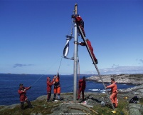
WS-0,30A8 installation in Norway.

